

Desktop PC tower in Autodesk Inventor: assembly, drawing, BOM
SphereHarness builds a 15-part PC tower in Inventor, mates it, clash-checks 171 pairs, then makes the assembly drawing and an Excel BOM.

The video plays from YouTube’s privacy-enhanced player only after you click it.
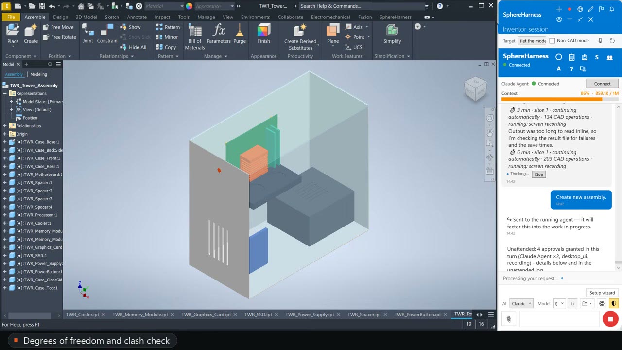
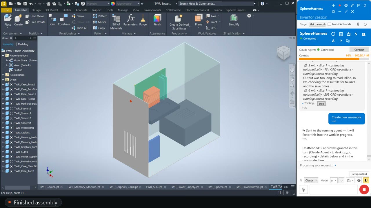
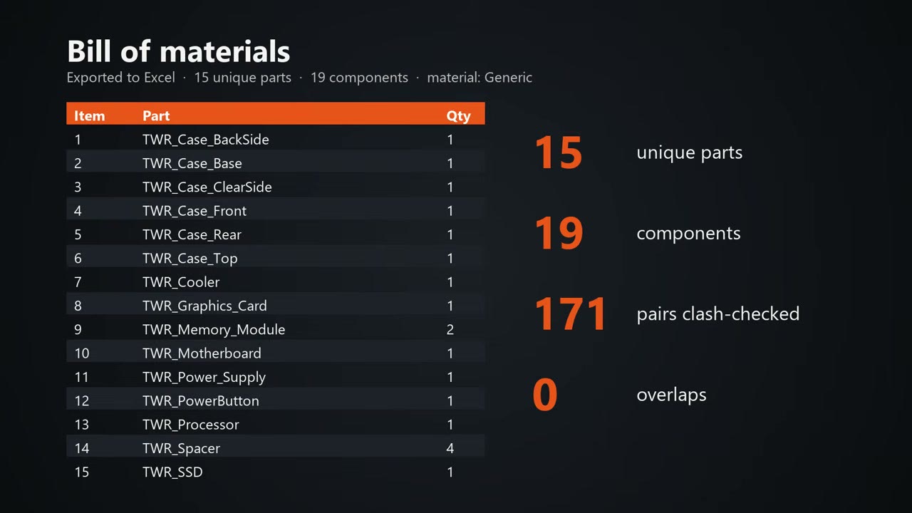
SphereHarness built a desktop computer tower in Autodesk Inventor from plain-English requests: case, motherboard, processor, cooler, memory, graphics card and power supply, then mated them into one assembly. The clash check covered 171 pairs and found no overlaps. The same session produced an assembly drawing and an Excel bill of materials with 15 unique parts and 19 components.
What was asked
Every step was a request typed into the SphereHarness chat panel docked beside Inventor: the case first, then the front panel, the electronics, the assembly, the drawing and finally the bill of materials. The video shows the agent working through them in that order without any command typed in Inventor itself.
What the agent did
Each part starts as a fully defined sketch. The case is a rectangle with its dimensions anchored to the origin, extruded into a base, a top cover and a back panel. The front panel adds five vent slots and a button opening, and 20 dimensions pin the slot sketch.
The electronics follow. The motherboard has four mounting holes, the cooler has eight fin channels, the graphics card has two fan recesses and the power supply has a vent grill. Round parts take a circle offset from the origin so their position is dimensioned too, and the spacer is two concentric circles extruded.
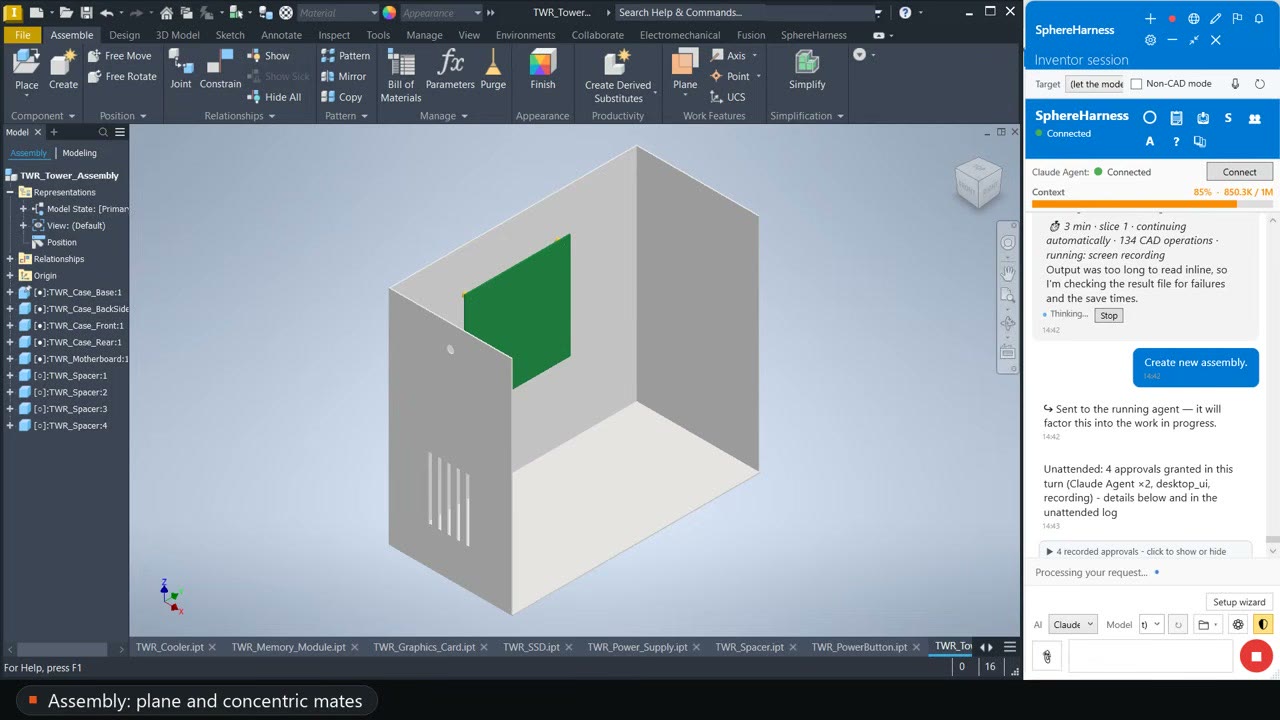
For the assembly the case base is grounded. Every other part is placed and mated to it, with plane mates for position and concentric mates for the spacers and the power button.
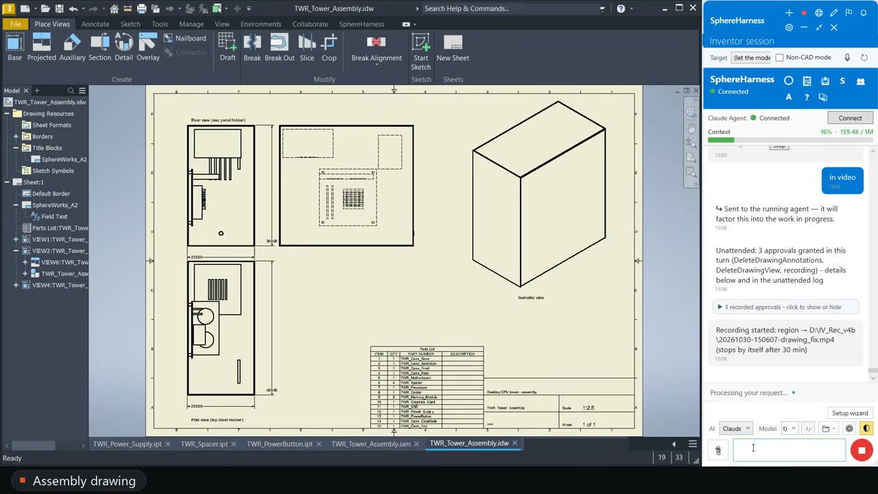
The drawing came next: views projected on one sheet, a parts list of 15 lines, dimensions on the overall size and the power supply, and a PDF export. The side view is projected from the rear view, so the two line up at the same height.
What we measured
- Every sketch read back as fully constrained; the cooler measured 68,400 mm³, the value it was designed to.
- The read-back after mating showed 14 components fully constrained.
- The clash check covered 171 pairs and reported 0 overlaps.
- The bill of materials exported to Excel lists 15 unique parts and 19 components.
What did not work
Nothing failed on screen, but one limit is stated in the video: the four spacers and the power button keep one rotational freedom after mating. For round parts that is harmless, so the agent left it.
Try it yourself
SphereHarness for Autodesk Inventor is described at /inventor, and /help/getting-started walks through the first install and the first request.